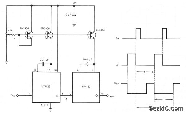

When the input power is applied the capacitor C2 charges through resistor R2 and when the voltage across the capacitor just exceeds.

The working of this circuit is very simple. This circuit is a very handy one and can be employed in many applications. We can also connect a Relay to trigger the AC appliance after the time delay. The circuit diagram shown here is of a simple DC power delay circuit that is based on an SCR. We can alter the time delay using a potentiometer. The Blue LED glows in an unstable state and Red LED glows in the stable state. And the current limiting to about 41 milliamps. With these components R1, R2, C1, and C2. It is transformed to the lower voltage, 220 volts to 15 Volts. When 220-volts power inputs to the circuit. It uses contact of the relay to act switches on-off to a load. As value changes, the time delay for the unstable states also is changed. The simple delay turn on the monitor circuit.

The time delay for the unstable state depends upon the value of the capacitor and resistor. Until and unless the start button is pressed and capacitor c1 is in a discharged state. when no button is pressed the output of the 555 timer IC is low and the circuit remains in a low state. When the input power is applied the capacitor C2 charges through resistor R2 and when the voltage across the capacitor just exceeds the Zener diode D3’s breakdown voltage, it breaks down and the SCR H1 is triggered and the delayed power will be available at the delayed OUT terminal. The circuit is powered via a voltage regulator. This circuit is a very handy one and can be employed in many applications. THRESHOLD: This pin determines when it is required to reset the flip-flop in the timer.ĭISCHARGE: If the o/p gets low or the flip-flop gets into a reset state, the discharge pin is dragged to the ground.Ĭircuit Diagram Working of Time Delay Circuit: When comparator’s o/p gets high, we get high voltage a the timer output too.Ĭontrol Pin: This pin connects to the -ve i/p pin of comparator 1. Due to the new CPLD and new software, our simple multiplexer circuit (written in Verilog) still works but has timing issues. V0 is the supply voltage or the Vcc R is the discharge resistance () which is connected parallel to the capacitor. The comparator’s o/p connects to the SET pin of the flip-flop. PURPOSE: To surely perform even the photometry of pulse light with simple constitution by providing a delay means to one of two sets of transistors for amplification of photo detecting current. The CPLD weve selected to use is the 3000A with a pin to pin delay of 10ns. Calculating the Delay To calculate the delay produced by the RC constant we can use the following formula: V V0 x e(-t/RC) V is threshold Voltage at which the mosfet is supposed to just switch OFF or just begin turning ON. TRIGGER: This pin is pulled from the -ve I/p of comparator 2.


 0 kommentar(er)
